Device Manual
The full reference for operating a CollarID Mk II — every LED state, the complete setup path, and the troubleshooting cases. For the 30-minute happy path, see the Quick Start.
Device anatomy
Familiarising yourself with the parts of the CollarID Mk II makes every later procedure easier — every section below references components by the names introduced here.
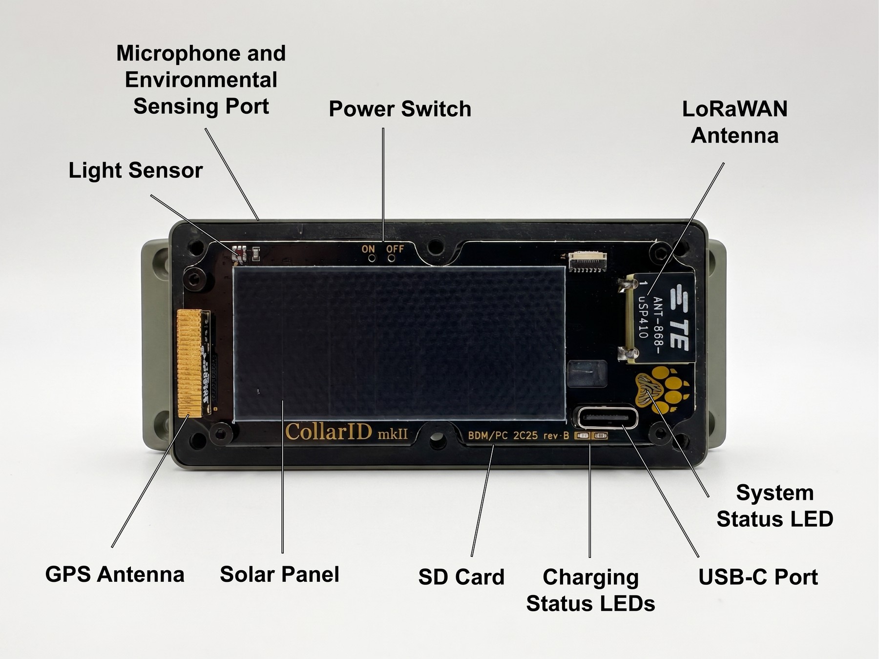
Components
- System status LED — the illuminated paw print on the top face. Reports boot, GPS, BLE, and fault states. Visible through the closed cover.
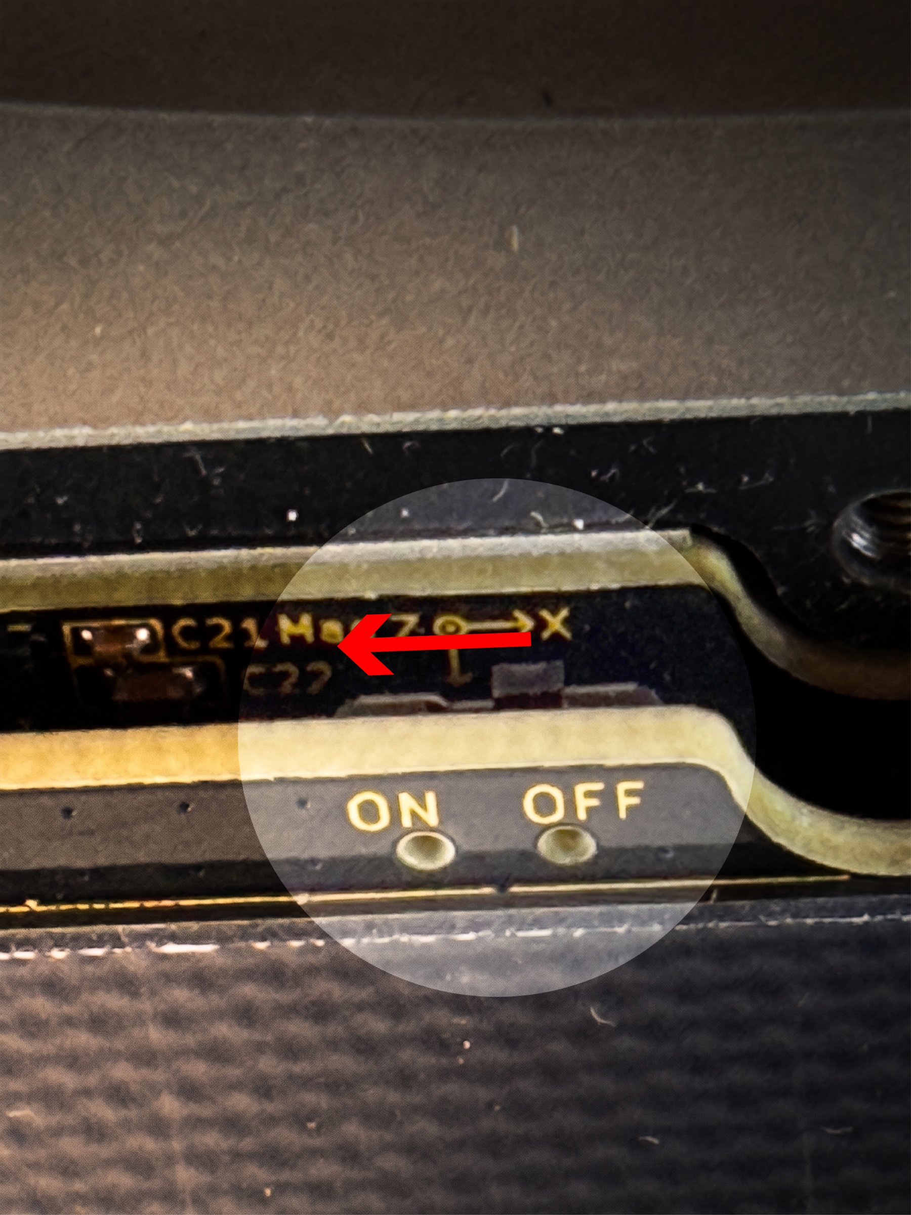
- Power switch — on the front PCBA, accessible only with the cover removed. ON / OFF labelled in silkscreen.
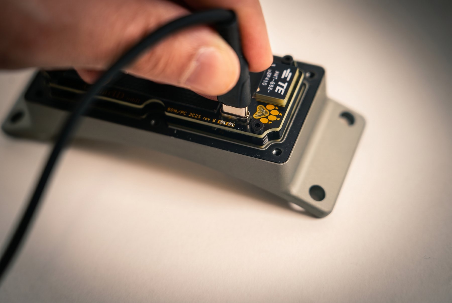
- USB-C port — on the top edge of the front PCBA, used for both charging and firmware updates. Cover must be removed to access it.
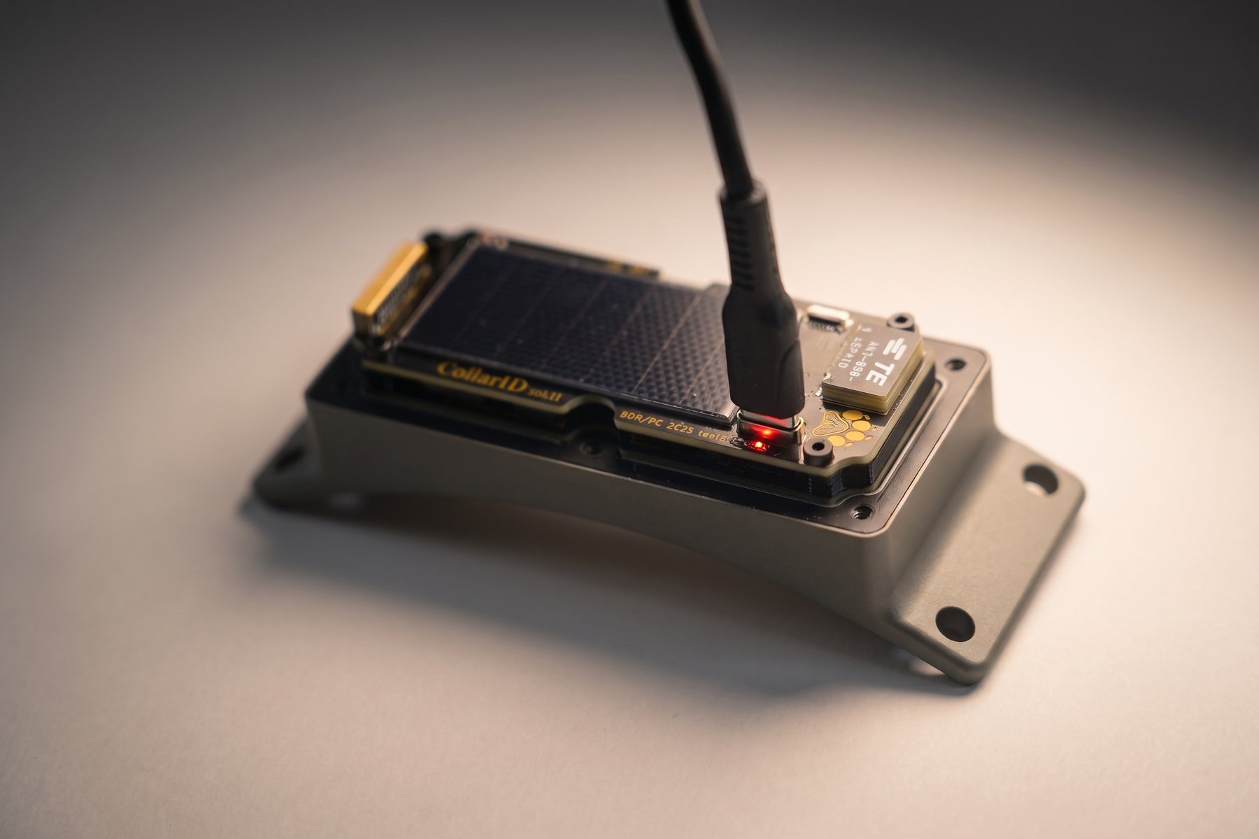
- Charging status LEDs — red and green LEDs inside the device, near the USB-C port. Visible through the closed cover.
- SD card — spring-latched push-push slot on the side of the front PCBA, accessible with the cover removed. Holds schedules, configuration, and recorded data.
- Solar panel — on the top of the cover. Charges the internal battery whenever exposed to light.
- GPS antenna — integrated patch antenna that drives the multi-GNSS receiver.
- LoRaWAN antenna — chip antenna for the long-range sub-GHz LoRa / LoRaWAN radio.
- Light sensor — ambient light sensor on the cover, used for diel-cycle and canopy-shading research signals.
- Microphone & environmental sensing port — routes the PDM microphone to the outside air and exposes the BME688 to ambient temperature, humidity, pressure, and gas (VOC) signals. The port is acoustically open but mechanically protected.
- Six perimeter cover screws — compress the gasket against the aluminum base for sealing.
Pre-flight checklist
Run through this list before sending a device into the field. Most field failures trace back to one of these items.
The list below covers what you check by hand. For what the device reports about itself — battery, storage, and the result of its power-on self-test — connect it to the Pre-Flight Check page and work through both lists. Those live checks need only Bluetooth, so they work from a laptop in the field without signing in; signing in adds the device’s recent transmission history and lets you record a sign-off for the deployment.
Opening & closing the enclosure
Most procedures in this manual begin with removing the cover. Treat the polycarbonate cover and the gasket carefully — they are what make the device water resistant.
Opening
- Lay the device on a clean, flat surface, top side up.
- Loosen all six cover screws — order doesn’t matter on the way out.
- Once all six are loose, fully remove them and set them aside in a small container so you don’t lose them in the field.
- Lift the cover straight up off the gasket. Avoid tilting or prying — the gasket can stretch or roll out of its channel.
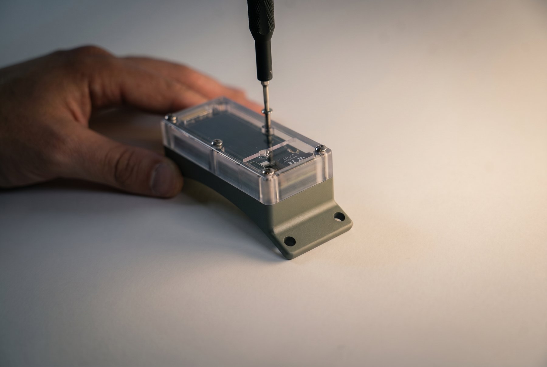
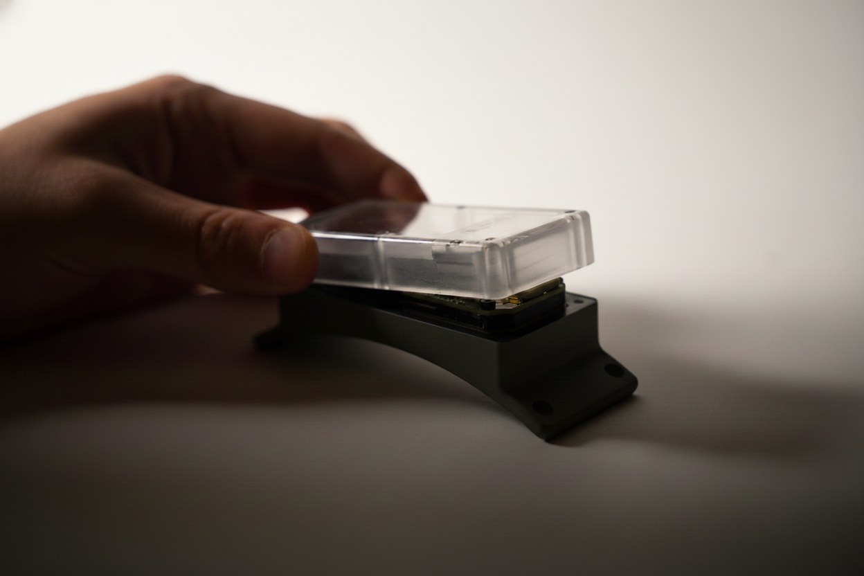
Closing
- Confirm the gasket is clean, undamaged, and fully seated in its channel before lowering the cover.
- Lower the cover straight down so the gasket is compressed evenly all the way around.
- Start all six screws by hand a few turns each, then snug them in a star pattern so the cover seats flat.
- Hand-tighten in the same star pattern. Stop as soon as the cover is firmly closed and the gasket is engaged. Do not over-tighten.
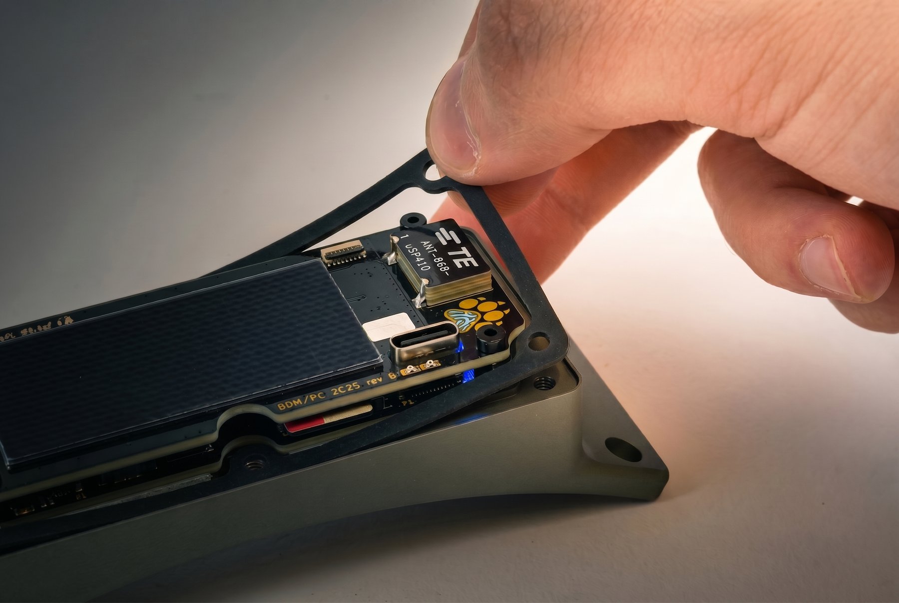
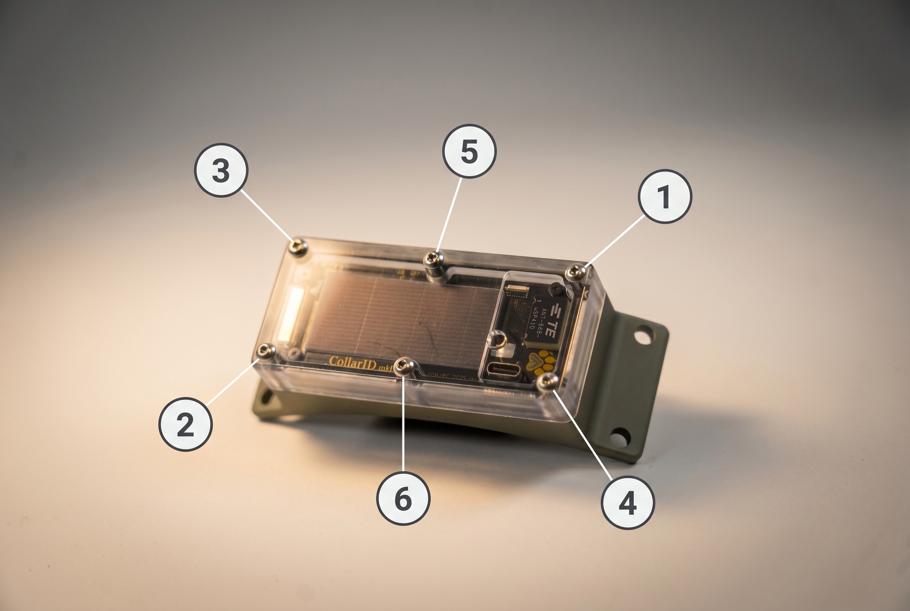
Hand-tighten only. Do not use an electric drill or impact driver to close the cover. The polycarbonate is strong but the threads are easy to over-drive, which can crack the cover or strip the inserts. If a screw bottoms out and you can still turn it easily, stop — it’s tight enough.
Powering on & off
Open the enclosure (six perimeter screws), insert a freshly formatted exFAT SD card, and slide the side power switch to ON (silkscreen-labelled on the front PCBA). Power on outdoors so the device can acquire its first GPS fix and sync its clock. To power off, slide the switch to OFF; no soft shutdown is required.
LED reference
The status LED (paw print, top of cover) and the charge LEDs (red + green, near USB-C) communicate device state. This is the canonical reference.
Charging via USB-C
Open the enclosure (the cover must be off — there is no pass-through) and connect a USB-C data cable to the port on the top edge of the front PCBA. The charge LED is red while charging (400 mA, ~2-hour full profile) and green when full. Charge-only cables are the most common reason charging won’t start.
Low-battery hibernation
If the battery falls to roughly 10 % SoC during a deployment, the firmware enters a hibernation mode rather than dying outright. While hibernating, the device wakes every 8 hours, samples the battery, and goes back to sleep if SoC is still below threshold. As soon as solar (or a USB-C top-up, if you’ve retrieved the unit) brings the battery above 20 % SoC, normal scheduled operation resumes automatically.
A flat collar in the field is recoverable on its own. A unit that has gone dark under canopy or after a stretch of overcast weather will resume on its next sunny day without you having to retrieve it — “no telemetry” does not necessarily mean “device lost.”
SD card notes
The SD card is where schedules, configuration, and recorded telemetry, audio, and accelerometer data live. Card quality has a direct impact on deployment reliability.
Inserting and removing the card
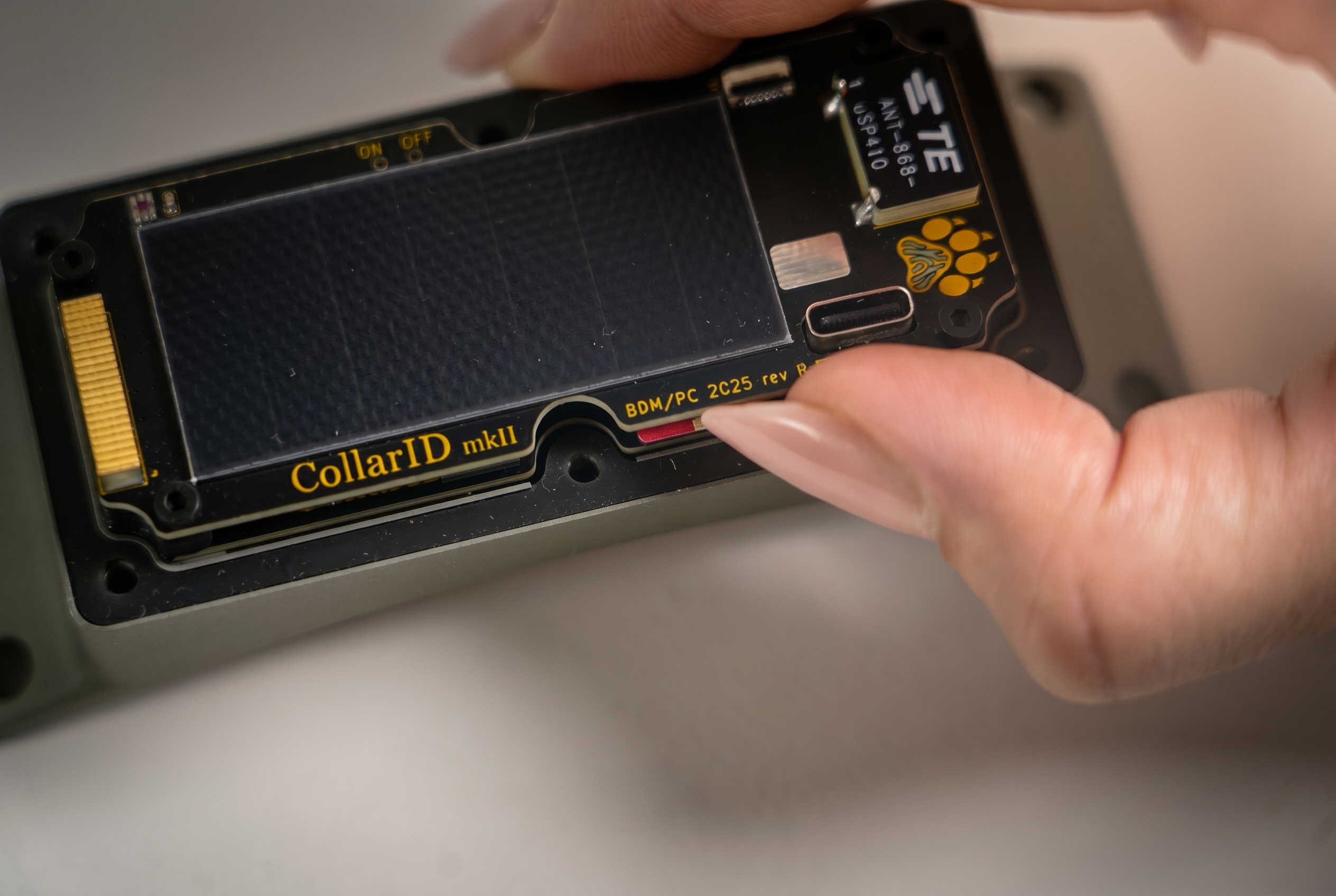
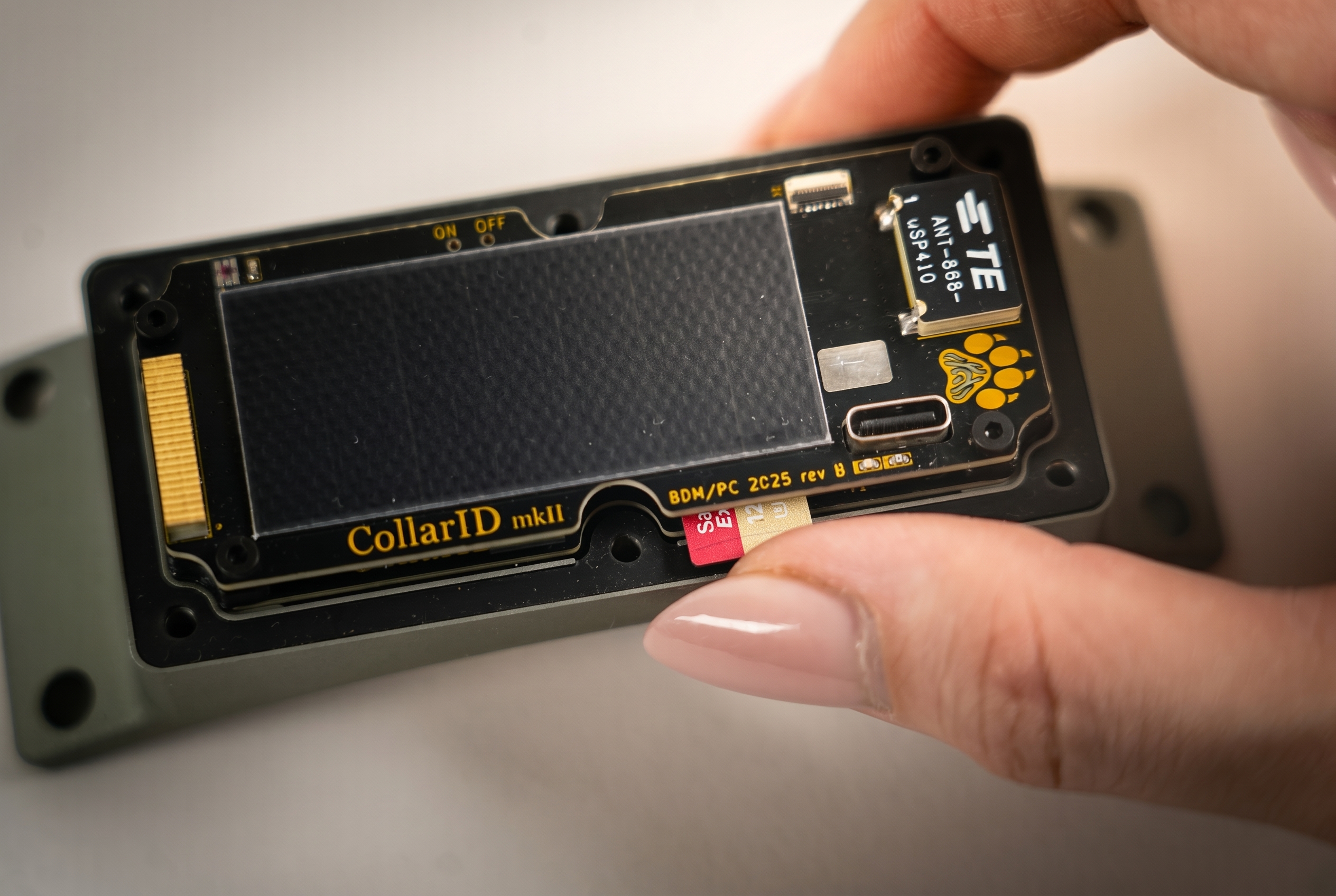
The slot is a spring-latched push-push mechanism on the side of the front PCBA; the cover must be removed to reach it (see Opening & closing). To insert: push the card in until you feel the spring catch. To eject: push the card in again — the spring releases and the card pops out far enough to grip.
Format
Cards must be formatted as exFAT — the only filesystem the firmware mounts. There is no formal capacity limit; we have tested up to 2 TB with no issues.
Recommended brands
- Kioxia Exceria Plus — our recommended card. Field-validated, and the firmware automatically picks the most efficient SD power profile when it detects this card on boot.
- SanDisk Extreme & SanDisk Extreme Pro — reliability limitations under continuous recording workloads. They will work, but expect at least double the microphone power consumption while audio is actively recording (the firmware has to keep the card powered through the whole recording window instead of dropping it between writes, to protect a more fragile flash controller) and a higher chance of file-system corruption over long deployments. The Extreme Pro initially looked comparable to the Kioxia in short tests but corrupted the same way as the standard Extreme once it had been running long enough — treat both as test-only.
- Other brands — untested.
Why card brand matters in the field — power, endurance, temperature
- Power-loss tolerance. Industrial cards survive sudden power drops without losing the last block of writes; consumer cards often corrupt the file system when power dips.
- Sustained write endurance. Continuous logging writes a card much harder than typical consumer use; cheap cards can fail silently after a few thousand writes to the same blocks.
- Temperature range. Field deployments swing through hot and cold extremes that consumer cards aren’t rated for.
- Controller behaviour. Consumer cards sometimes misreport free space, throttle unexpectedly, or pause for garbage collection — any of which can drop data on a real-time logger.
- Power consumption. Different cards draw very different amounts of power while idle but powered. The firmware also has to keep less-resilient cards energised longer between writes to protect them, which compounds the difference — in our testing, at least 2× the microphone power on a SanDisk Extreme / Extreme Pro versus the Kioxia Exceria Plus, directly cutting deployment battery life. The configurator’s power estimate shows the doubled figure when you toggle the unapproved-card scenario.
Want to use a different card?
If there’s a specific card you’d like to use that isn’t listed above, we recommend one of the following before putting it on an animal:
- Send us a sample so we can test it internally and add it to the firmware’s auto-detect list (the safest option).
- Or run it yourself for at least a week in a benchtop deployment that mirrors your intended schedule. Check that the card captured the expected data and that the device still boots cleanly at the end of the test.
If you do try a different brand or model and run into trouble, please report what happened to the team so we can document it.
Entering BLE mode
BLE mode is required to update the schedule or run a firmware update. There are two ways to enter it.
Method 1 · Insert a freshly formatted SD card
If the device boots with an SD card that has no schedule on it (a freshly formatted card), it enters BLE mode automatically once the boot sequence completes:
- Power off the device, open the enclosure, and insert a freshly formatted exFAT SD card.
- Power the device on.
- Wait for the boot animation, steady green (SD scan), then a steady cyan LED — this signals BLE mode is active.
Method 2 · Hold a magnet over the status LED
You can trigger BLE mode at any time, with the cover still on, using a magnet:
- Hold a magnet directly over the paw print on the top of the cover.
- Keep it in place for at least 3 seconds, then pull it away.
- The device resets and runs through the boot sequence: boot animation, steady green, then steady cyan (BLE mode).
Magnet strength. Any magnet strong enough to trip the internal sensor works. N52 neodymium magnets are reliable, but even a household refrigerator magnet held close has worked. If your magnet doesn’t trigger after 3 seconds, try a stronger one or hold it slightly closer.
BLE mode times out after 10 minutes. If you don’t connect within that window, the device exits BLE mode — entering low-power mode if no schedule is configured, or beginning its schedule if one exists on the card. Re-trigger BLE with a magnet swipe if you need more time.
Updating the schedule
Schedules live on the SD card. Place the device in BLE mode (see Entering BLE mode), connect from the web Configure tool (Chrome/Edge) or the iOS / Android apps, edit up to four recording windows with per-sensor settings, check the power-budget estimate, then send and disconnect. The schedule commits when the steady-cyan LED turns off (~10 s after disconnect) — the card-resident schedule is the source of truth.
Already deployed? You don’t need the collar in hand at all — see Remote schedule changes to edit a collar’s schedule over the air.
The “System Engaged” flag
Every schedule has a System Engaged toggle. This is what tells the device whether to start running the schedule or stay dormant waiting for you.
- On — the device begins running the configured schedule as soon as you disconnect from BLE. This is the standard “deploy now” setting.
- Off — the device enters an ultra-low-power dormant mode instead of executing the schedule. A fully charged battery can stay in this state for over a year. Wake it any time by swiping a magnet over the paw-print LED or flipping the power switch off and back on — both re-enable BLE automatically, so you can connect and flip System Engaged back on.
This lets you fully prepare a device ahead of time — load the schedule, close and seal the enclosure, even ship it — and then engage it in the field with a magnet swipe and a tap in the app. No need to open the device once it’s sealed.
Where to configure
Three configurator surfaces are supported. All three can edit schedules and show power estimates; only the website can update firmware.
Web BLE is only available on Chromium-based browsers such as Chrome and Edge — Firefox, Safari, and most mobile browsers don’t expose Bluetooth APIs, which is why the iOS and Android apps exist. Get the apps: CollarID on the App Store · CollarID on Google Play.
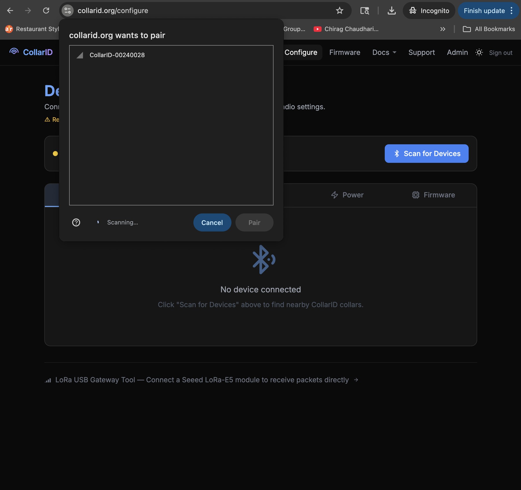
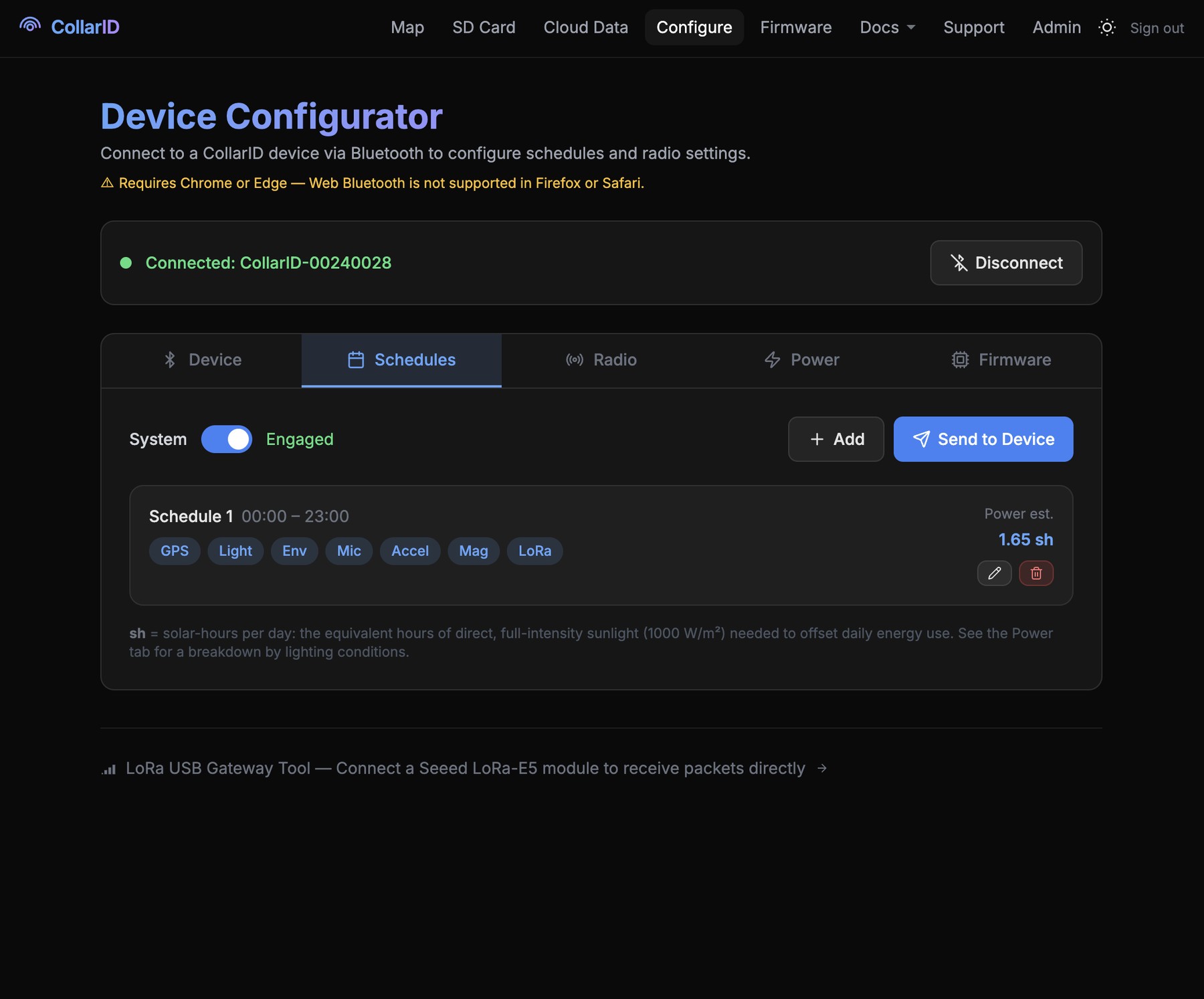
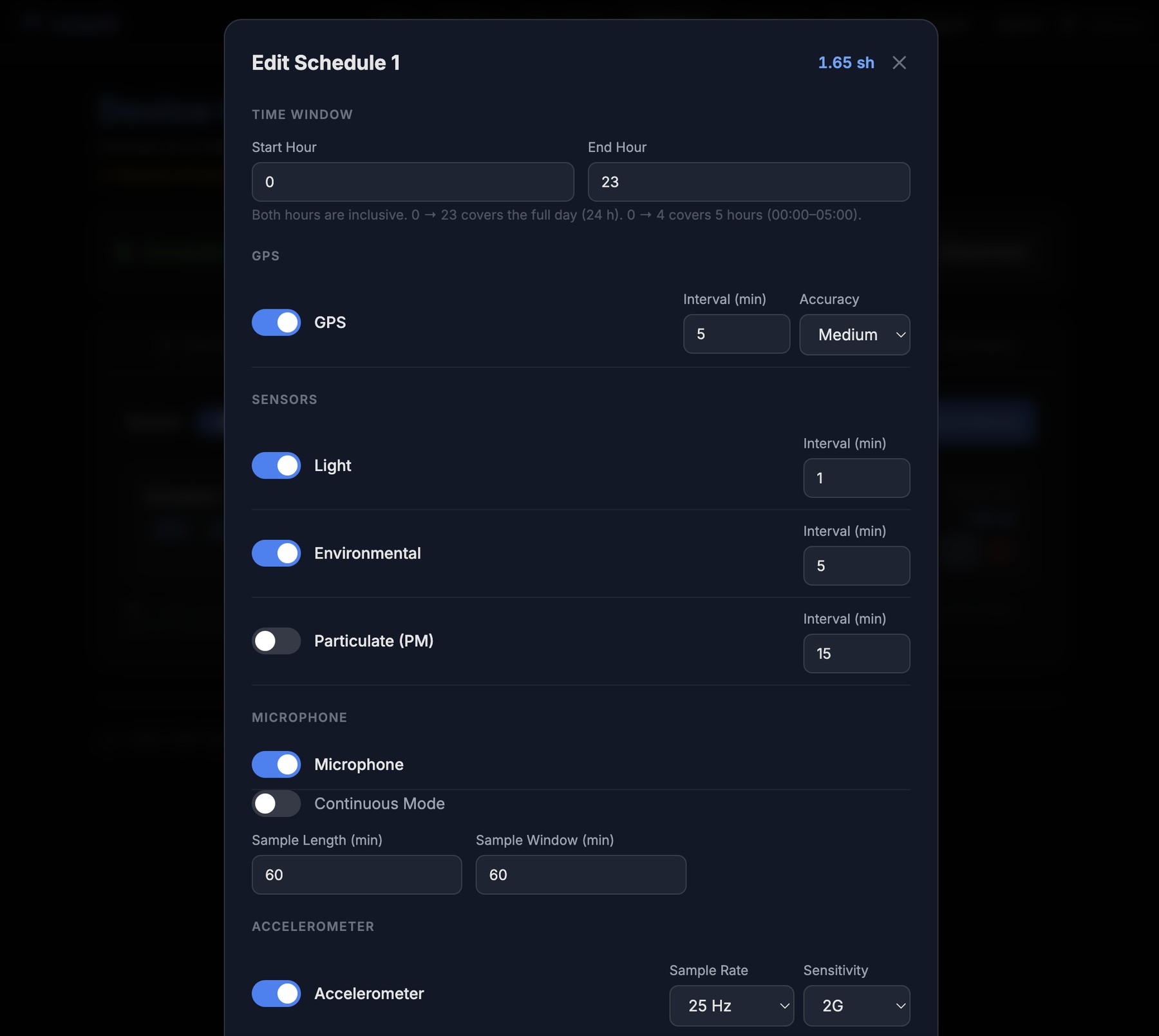

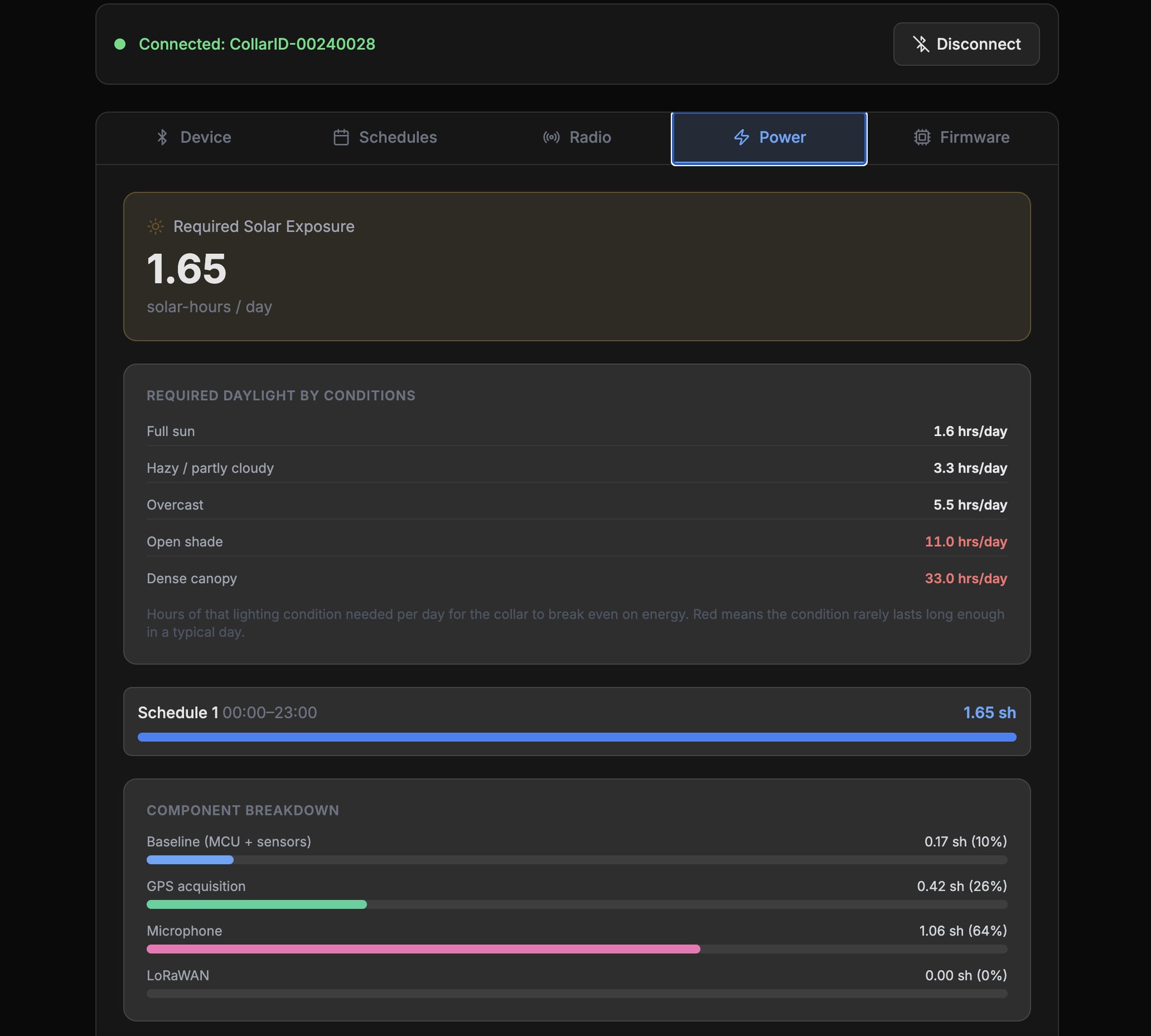
The Android app is visually identical to iOS — same screens, same labels — so a single platform walkthrough applies to both.
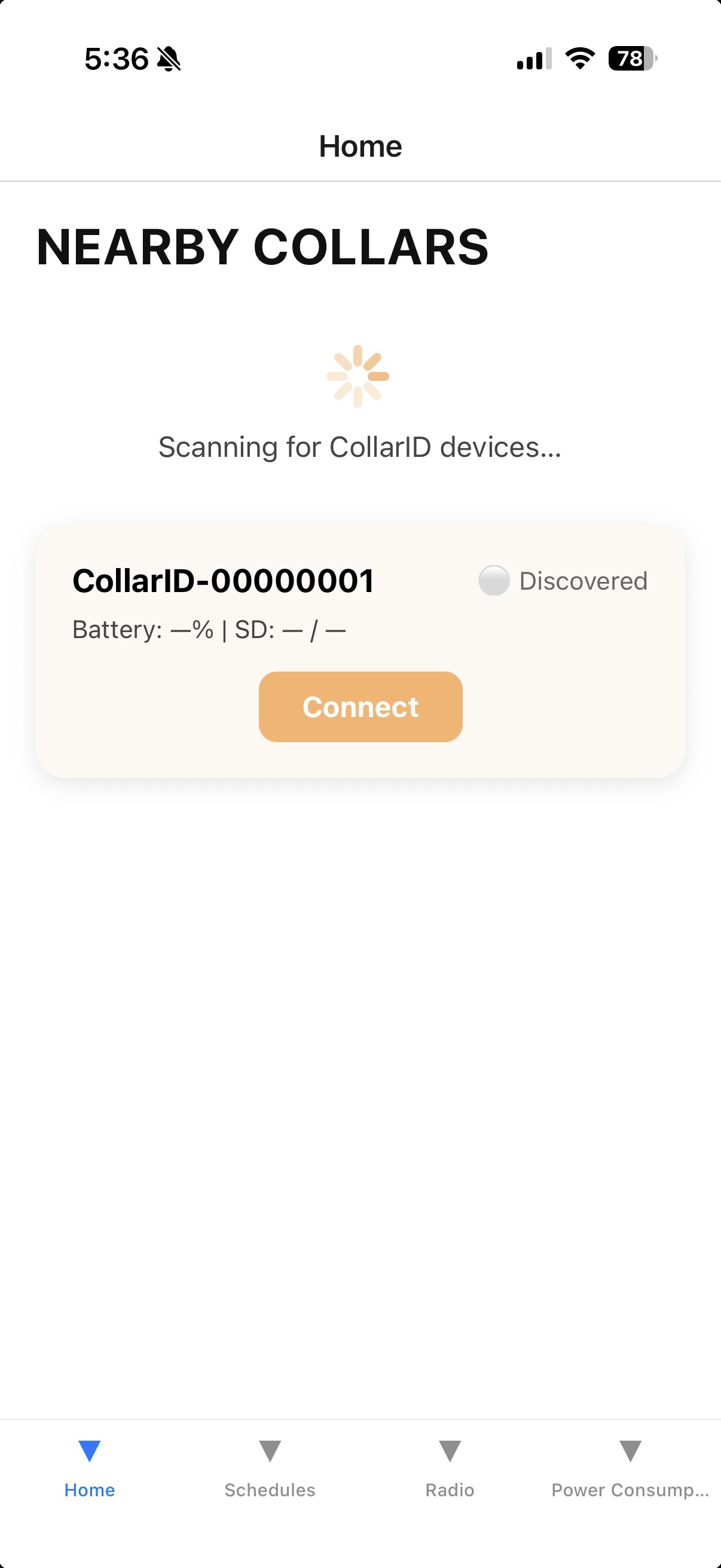
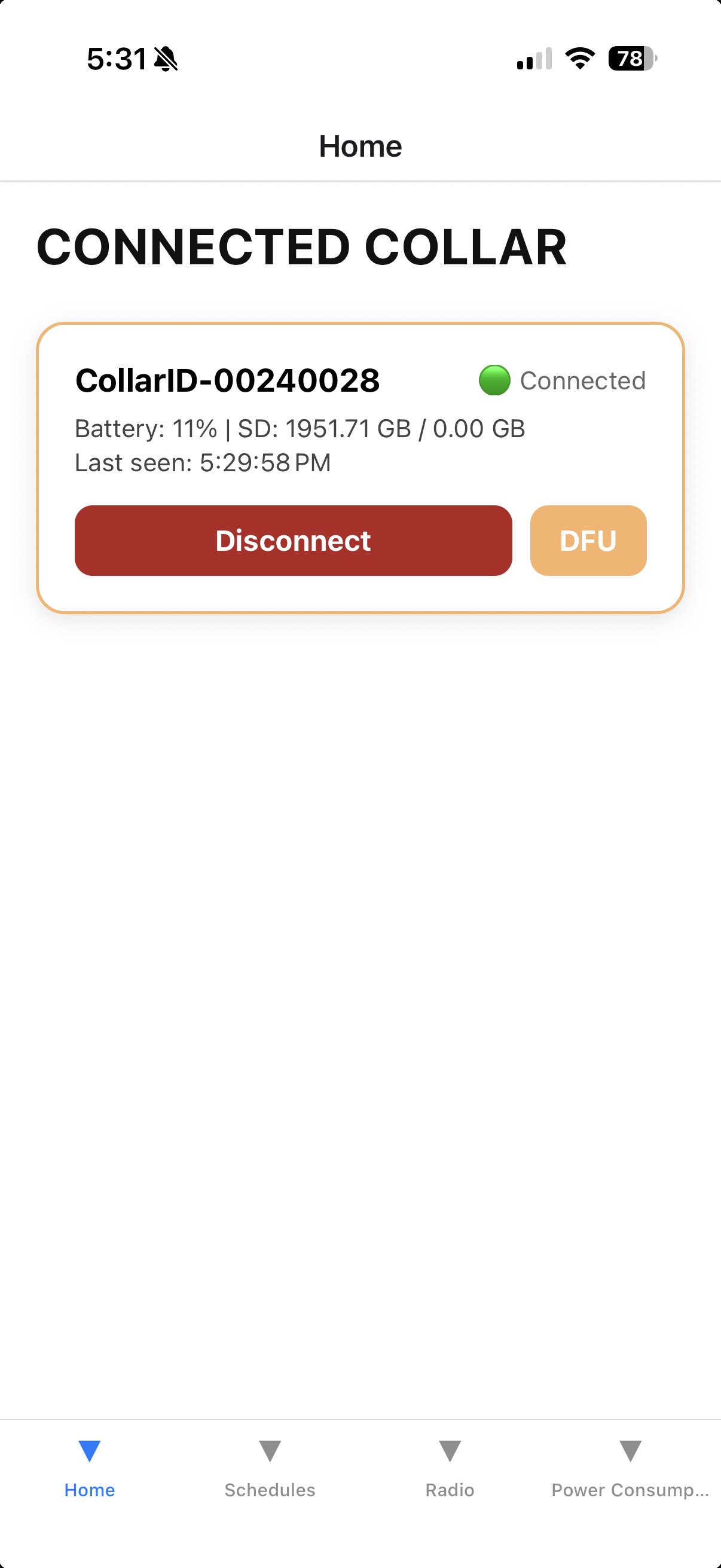
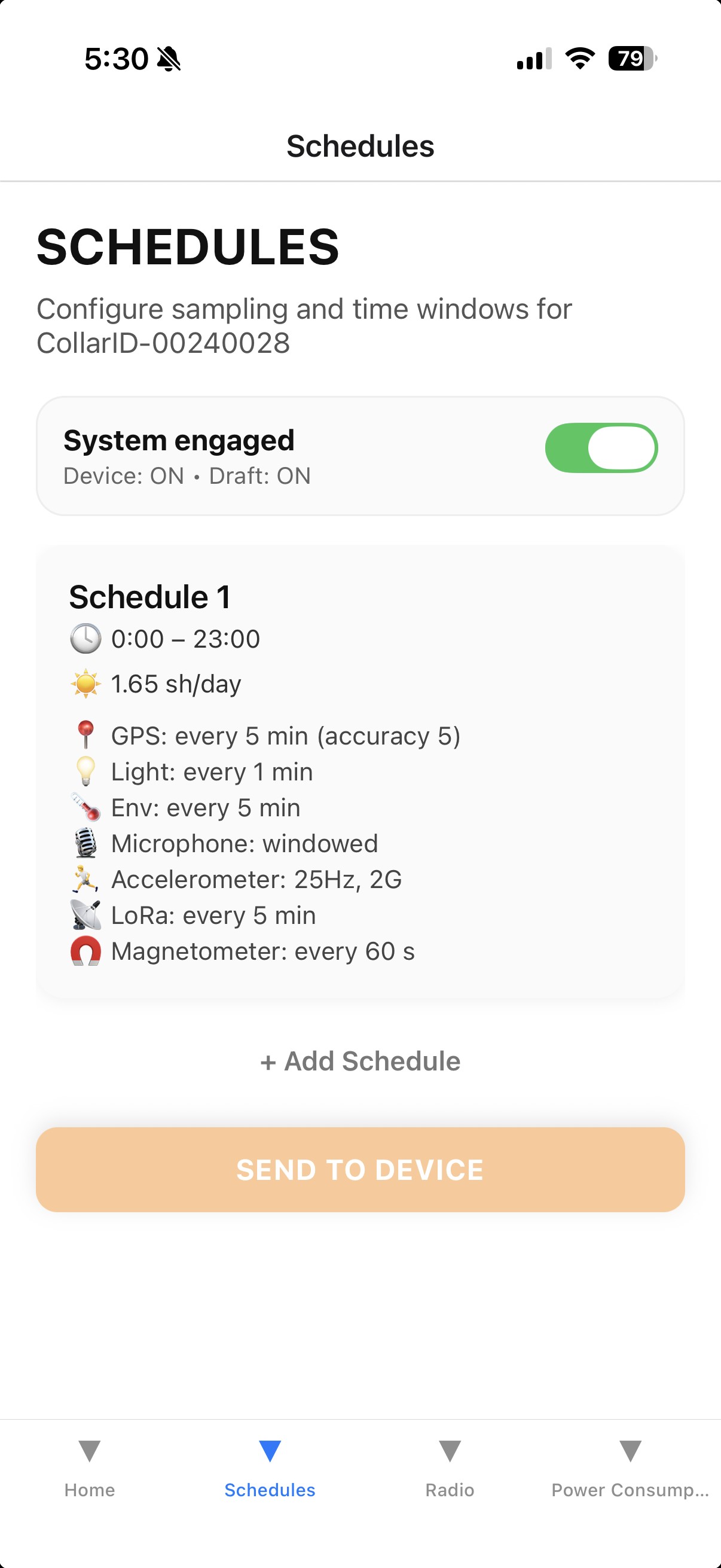
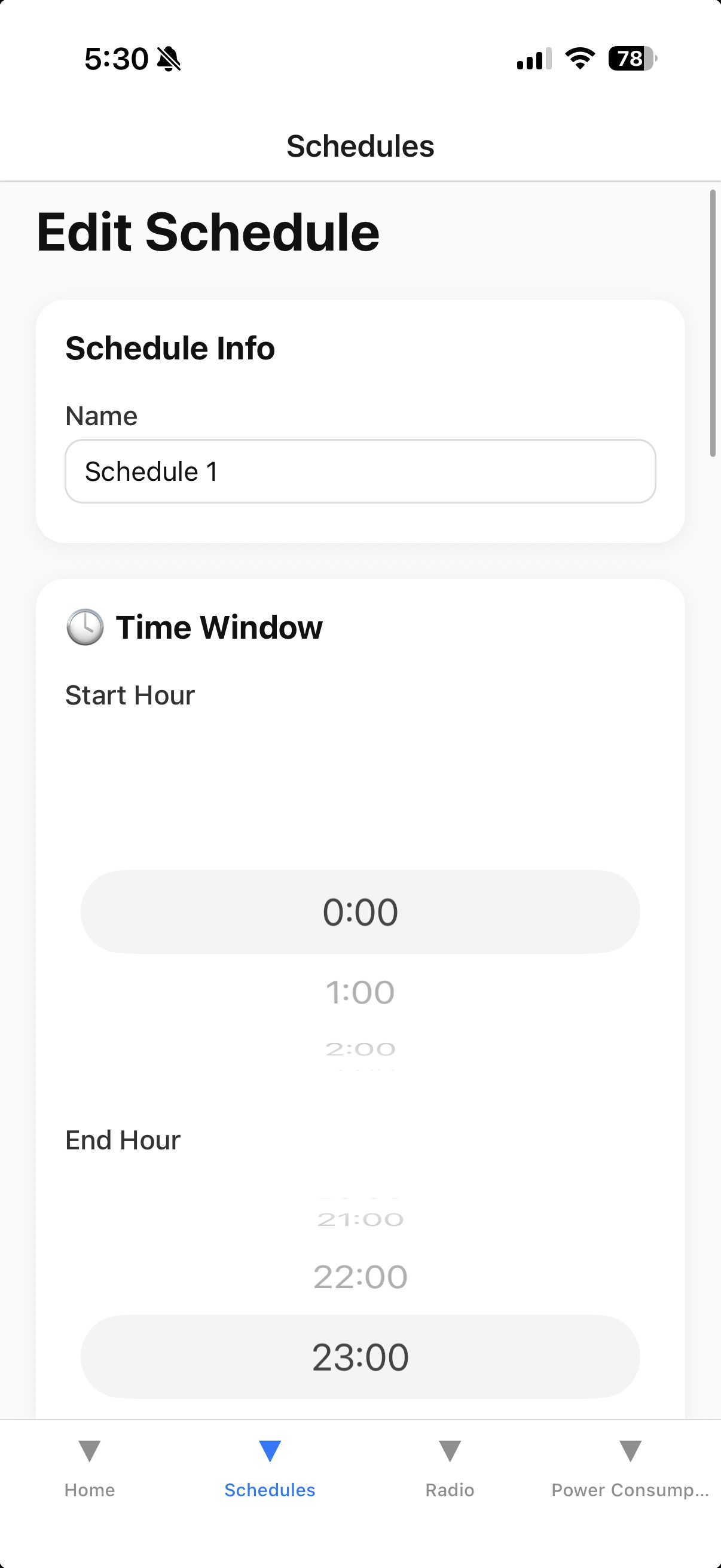
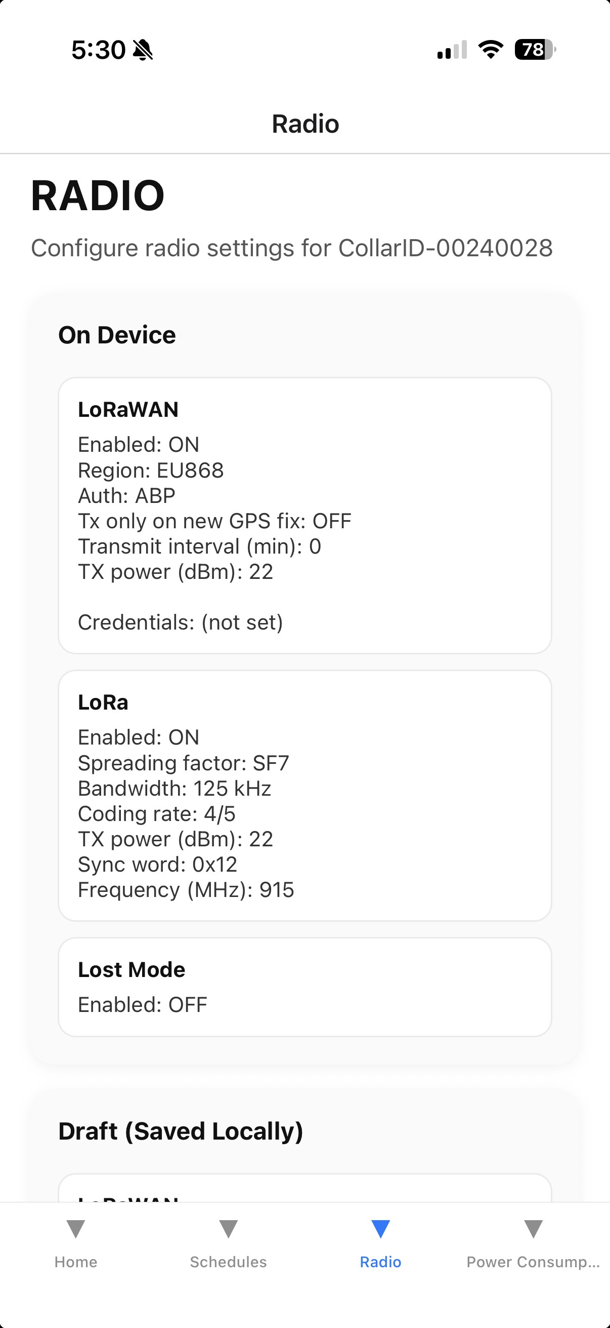
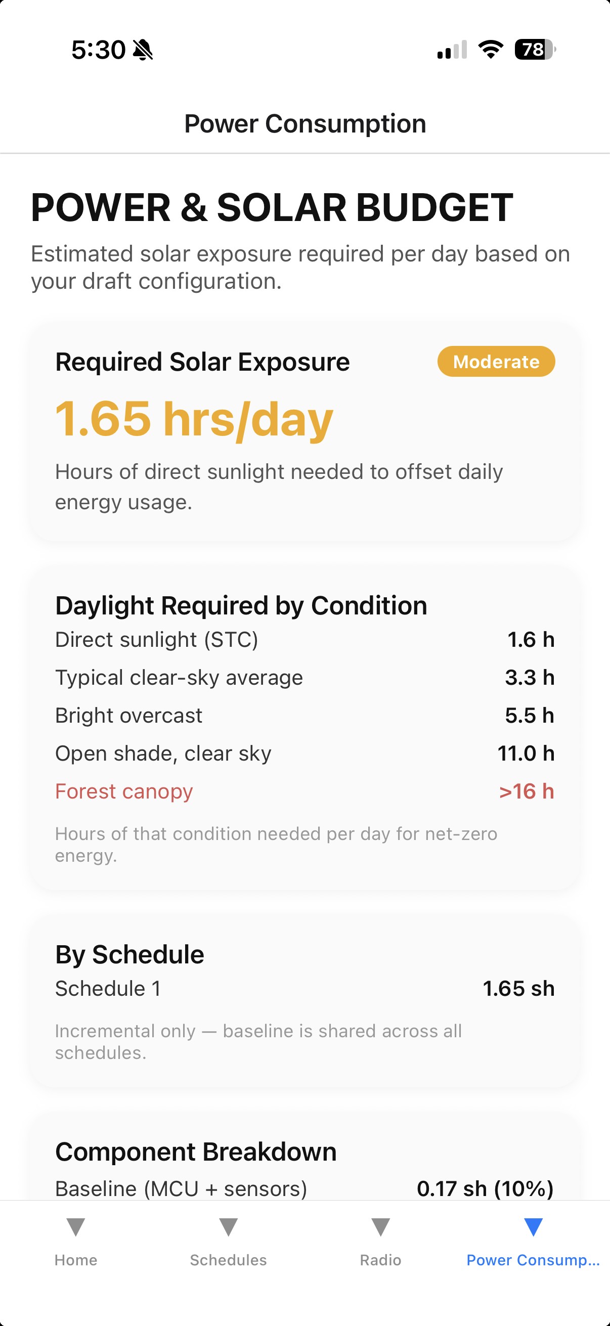
Send before you disconnect. Edits made in the configurator stay in the app until you explicitly push them to the device (Send / Apply / Save, depending on the platform). Once sent and disconnected, the steady cyan LED turns off ~10 seconds later — that’s when the new configuration locks in.
Remote schedule changes
Once a collar is deployed, you no longer need to recapture the animal to change what it records. The Remote Schedule page shows the schedule a collar is actually running — not just what you last configured — and lets you change it over the collar’s normal radio check-ins. No cable, no BLE, no handling.
What you need
- A collar on recent firmware (build 298 or newer unlocks everything described here; the page tells you if a collar needs an update and hides anything it can’t do yet).
- A LoRaWAN gateway in range of the collar, and the collar provisioned to your account.
How a change travels
Radio messages to a collar are small, so a schedule change is broken into pieces that ride along with the collar’s regular check-ins. Once a transfer starts, the collar briefly speeds up its check-ins, so most changes land within a few minutes. After applying a change, the collar reads its schedule back to you — the page always ends up showing what the collar is really doing, not just what was sent. While that read-back is in progress you’ll see a parts counter (e.g. “7/11 parts”) ticking up.
What you can change
- Any schedule setting — recording windows, GPS, microphone, other sensors, and how often the radio transmits, with the same power estimates and warnings as the regular configurator.
- Add or remove schedules — up to five. Any schedule can be removed, not just the newest one.
- Mortality detection — turn it on or off and tune how long the collar waits before flagging, collar-wide.
Built-in protections
- A collar will refuse any change that could silence it — turning every radio off, or checking in less than once a day. Those changes can only be made with the collar in hand, so a typo can never strand a deployed animal.
- Changes apply all-or-nothing. If any piece of a transfer goes missing, the collar rejects the whole change, keeps running its current schedule untouched, and the transfer starts over on its own.
- Interrupted transfers recover by themselves. Radio messages get lost in the field — that’s normal. The system notices and retries automatically; you never need to babysit a transfer.
Reading the status badge
- IN SYNC — the page is showing exactly what the collar is running. Safe to edit and push.
- AWAITING REPORT / receiving parts — the collar is describing its schedule; the counter ticks up with each check-in. Just wait.
- VERIFYING PUSH — your change was applied and the collar is reading it back for confirmation.
- MODIFIED ON DEVICE — someone changed the schedule with the collar in hand (SD card or BLE); the page is catching up.
- REPORT STALLED — the collar restarted mid-report (usually a firmware update). Recovery is automatic; nothing to do.
Time windows now include their end hour. On firmware build 298 and newer, a schedule window that ends at 18 runs through 18:59 — the way most people read it, and the way the power estimates always calculated it. Older collars stop at 17:59 instead. The Remote Schedule page knows which way each collar reads its windows and displays the day-coverage bar accordingly, so what you see always matches what that collar will do.
Dynamic GPS sampling
By default, the GPS takes a fix on a fixed timer regardless of what the animal is doing. Dynamic sampling lets the collar adjust that timer automatically based on movement — sampling more often when the animal is active and slowing down when it is resting. This can meaningfully reduce battery drain compared to a fixed high-frequency schedule.
How it works
When dynamic sampling is enabled, the collar’s built-in accelerometer continuously measures overall body acceleration (VeDBA — Vectorial Dynamic Body Acceleration) once per second, even if accelerometer recording is not turned on. You configure two movement tiers:
- Medium motion — triggered when VeDBA exceeds a threshold you set. The collar switches to a faster GPS interval for this tier.
- High motion — triggered when VeDBA exceeds a second, higher threshold. The collar switches to an even faster GPS interval.
- No motion — when VeDBA stays below the medium threshold, the collar uses the standard GPS interval you already configured.
The collar automatically moves between these three states as activity changes. Upgrading (still → moving) happens immediately; downgrading (moving → still) requires five consecutive seconds below the threshold to avoid flipping back and forth on brief pauses.
Short bursts of movement are still captured. Even if an animal moves briefly and returns to rest before the next GPS check, the collar remembers the peak activity level seen since the last fix and still fires at the faster rate. A sprint lasting only a few seconds will not be silently missed.
Configuring in the schedule editor
- Enable GPS and set the Interval — this becomes the no-motion rate (e.g. 180 min for a resting animal).
- Toggle Dynamic sampling (activity-based) on. A panel appears with four fields.
- Set Medium VeDBA threshold and Medium interval — the GPS rate for moderate movement (e.g. walking).
- Set High VeDBA threshold and High motion interval — the GPS rate for vigorous movement (e.g. running).
VeDBA thresholds — what values to use
VeDBA thresholds are entered in units of 0.01 g (where g is the acceleration due to gravity, 9.8 m/s²). Typical starting values:
These are rough guides only. Thresholds vary substantially by species, body size, and how the collar is mounted. Download a short accelerometer recording during known behaviours and inspect the VeDBA values to calibrate thresholds for your study animal.
The accelerometer runs in the background whenever dynamic sampling is enabled — it does not create accelerometer recordings on the SD card unless you also explicitly enable the Accelerometer sensor in the same schedule. Background activity monitoring has negligible power draw.
GPS-triggered LoRaWAN transmission
Normally, LoRaWAN packets are sent on a fixed timer (e.g. every 60 min) regardless of whether a new GPS fix has arrived since the last transmission. GPS-triggered TX bypasses this timer: the collar only transmits a LoRaWAN packet immediately after it acquires a fresh GPS fix, ensuring every packet over the air carries a confirmed, current position.
When to use it
- Studies where you care only about confirmed locations, not heartbeat check-ins.
- Dense-canopy environments where GPS fixes are infrequent — the collar transmits whenever it can get a fix, rather than sending stale coordinates on a timer.
- Paired with dynamic GPS sampling so transmissions cluster around periods of movement.
Enabling GPS-triggered TX
GPS-triggered TX is set in the Radio Config section of the configurator, not in the per-schedule editor. Open the Radio Config panel and turn on GPS-triggered TX under LoRaWAN. When this is on, the transmit-interval setting is ignored — the collar transmits once after every successful fix instead.
GPS-triggered TX requires LoRaWAN to also be enabled in the schedule (under Radio, per schedule). The Radio Config enables the feature globally; the schedule toggle enables the radio hardware during that time window.
Configuring without Bluetooth (CONFIG.CSV)
The device reads its settings from a CONFIG.CSV file on the SD card root at every boot. You can build or edit that file directly in the web configurator — no device connection required. This is useful when:
- the browser won’t connect to a device over Bluetooth;
- you’re prepping several cards with the same settings at a bench;
- you want to check that existing CONFIG.CSV files are valid — import one and confirm it loads without errors.
Export a new config
- Open the configurator and click Work Offline (no device needed).
- Build your schedules and radio settings exactly as you would when connected.
- Click Export CSV. On Chrome / Edge a Save dialog opens — save the file (named
CONFIG.CSV) to the root of the SD card, or anywhere and copy it over.
The file must be named exactly CONFIG.CSV. If your browser downloads it as CONFIG (2).csv because an old copy is in your Downloads folder, rename it before copying it to the card. (Recent firmware will also recover a stray CONFIG….csv automatically, but don’t rely on it.)
CONFIG.CSV replaces the device’s entire configuration on next boot, including the LoRaWAN keys. The configurator can’t fetch those keys — they’re unique to each device’s identity — so a config you build from scratch has blank keys and will break LoRaWAN unless you enter them by hand.
Edit an existing config (keeps the keys)
To change only the schedule without re-typing keys, start from the card’s current file:
- Copy
CONFIG.CSVoff the SD card. - In the configurator, click Import CSV and choose that file — your schedules and radio settings (including the existing keys) load into the editor.
- Make your changes, click Export CSV, and copy the file back to the card root.
On the next boot the device applies the file and rewrites it with its own bookkeeping — so the firmware version and device UID lines you see in an exported file are just placeholders and are safe to ignore.
Your own LoRaWAN gateway
CollarID devices report telemetry over LoRaWAN. To receive that data you need a LoRaWAN gateway within range of your collars, pointed at a network server. CollarID hosts a server for free for small-scale testing — you supply a gateway and an antenna, point the gateway at the CollarID server, and your collars’ uplinks start flowing into your account.
The free CollarID server is intended for small-scale testing. For larger or long-term deployments, contact the team at [email protected] to discuss options.
Data visibility. If you route your collars’ LoRaWAN telemetry through the CollarID server and view them in the CollarID dashboard, the CollarID team can also see your devices’ location and sensor readings — this does not include accelerometer or microphone data. It is never shared with anyone else, and is used only for diagnostics and troubleshooting.
What you need
- A LoRaWAN gateway for your region (US915 or EU868 — they are not interchangeable).
- An antenna matched to that region, ideally mounted outdoors with a clear sky view for the best range.
Recommended hardware
Antenna. For outdoor applications we often recommend an omnidirectional antenna with a lightning arrestor — many equivalent variants exist, such as a RAIGEN omnidirectional outdoor antenna with lightning arrestor or a comparable model.
Gateway. For our own deployments we use the SenseCAP Multi-Platform LoRaWAN Gateway (SX1302) for its low cost and ease of use — order the variant for your geographical region (US915 vs EU868).
The SenseCAP model above is an indoor gateway. For outdoor use it must be housed in a weather-tight enclosure or placed inside a structure, with the antenna connected to it and ported to the outside.
Pointing the gateway at the CollarID server
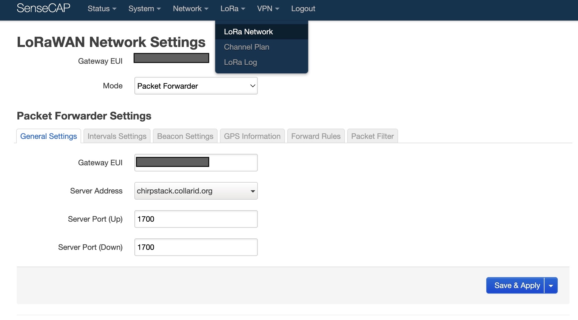
As an example, to configure a SenseCAP gateway to talk to the CollarID server:
- Log in to the gateway’s console.
- Select LoRa → LoRaNetwork.
- Open General Settings and set the Server Address to
chirpstack.collarid.organd the Server Port (up and down) for your region —1700for EU868,1701for US915. Set the same port for both fields. - Leave the EUI as-is. Send that EUI to the CollarID team at [email protected] so they can register your gateway on the network.
The port is region-specific: EU868 → 1700, US915 → 1701. Using the wrong port for your region means your gateway will connect but no collar data will be received. Your gateway must also be registered on the CollarID network before its data is accepted.
Updating firmware
Updates are done from the Update Device page in the web configurator (Chrome or Edge). Over Bluetooth is the normal way — the enclosure stays sealed and no cable is needed. Over USB-C works on every device ever shipped and is what you use to bring an older collar up to date the first time.
A collar has two updatable parts: the main processor, which runs the schedule and sensors, and the MKII Mesh radio, which handles Bluetooth and short-range links. The Update Device page lists them separately and tells you if either is out of date. Updating both in one sitting is normal.
The main processor updates over Bluetooth on v1.14.0 and newer. Older collars must be brought up to date once over USB-C — the page checks the version when you connect and tells you which applies, so you do not have to keep track. After that first cable update, every future one can be wireless. The radio module can only be updated wirelessly, and only if its own firmware is new enough; on a small number of early pilot units it is not, and there is no cable path to fix that — those radios need specialist programming equipment and have to come back to us.
Method 1 · Over Bluetooth (no cable, cover stays on)
- Place the device in BLE mode (see Entering BLE mode). Confirm the steady cyan LED.
- In Chrome or Edge, open the Update Device page, sign in, and connect to the device.
- Pick the version you want and start the update. Keep the device within a couple of metres of the computer and leave the page open.
- The transfer takes several minutes. When it reaches the end, the device checks the new firmware over before switching to it, then restarts on its own — the Bluetooth connection dropping at that point is expected.
- Reconnect and confirm the version shown has changed.
When the transfer reaches 100%, leave the collar alone. It spends a further ten to fifteen seconds checking the new firmware over before restarting itself. Resetting it or removing power during that window cancels the update. The page tells you when the restart has happened.
If the radio update fails within the first few seconds, the radio’s own firmware is too old to accept wireless updates. This is not a fault and nothing on the device has been changed — it carries on running its existing firmware. A cable cannot fix this: the radio has no USB-C update path and needs specialist programming equipment, so the device has to come back to us to have wireless updating enabled. Get in touch and we’ll arrange it. This affects a small number of early pilot units.
A failure partway through is different — simply retry. A device only ever switches to new firmware after it has verified the whole image, so an interrupted update leaves the existing firmware untouched.
Method 2 · Over USB-C (main processor — older collars, or recovery)
Bluetooth puts the device into firmware-update mode and the new firmware transfers over the cable. This works on every device ever shipped and updates the main processor — use it to bring a collar older than v1.14.0 up to date the first time, or to recover one. It cannot update the radio.
- Open the enclosure (six cover screws) — the USB-C port has no pass-through, so the cover must be off.
- Place the device in BLE mode (see Entering BLE mode). Confirm the steady cyan LED.
- Connect the device to your computer with a USB-C to USB-C data cable, plugged directly into the computer with no dongle, hub, or USB-A adapter in between. Many USB-C cables are also charge-only and won’t work — if unsure, use a cable that came with a phone or tablet.
- In Chrome or Edge, open the Update Device page and sign in. Connect to the device when it appears in the list.
- Put the device into DFU mode. The device will disconnect over BLE — this is expected.
- Select the firmware version you want and click Connect & Flash. When the browser prompts for a device, choose the one labelled DFU in HS Mode.
- The flash runs to completion and the device reboots into its normal boot sequence. Once you see the boot animation, disconnect, replace the cover, and close it up.
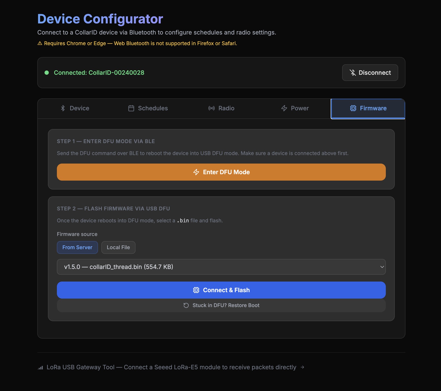
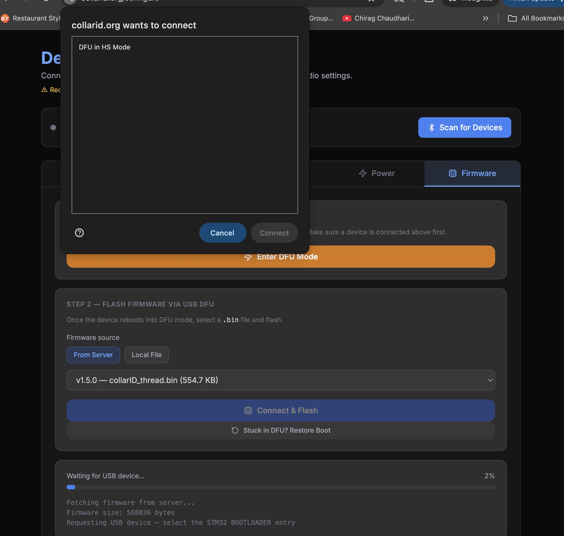
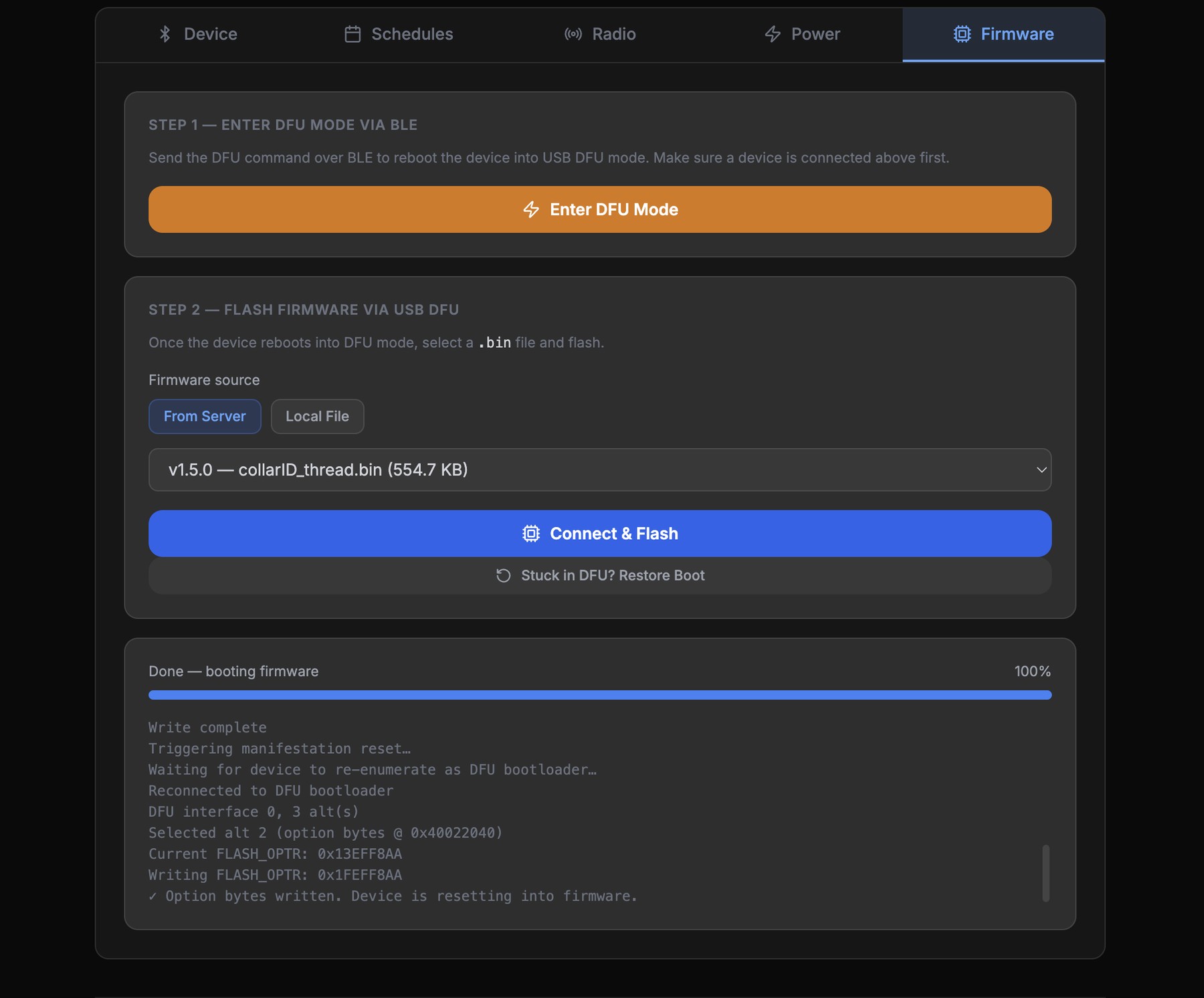
Use a USB-C to USB-C data cable plugged directly into the computer. Avoid dongles, hubs, and USB-A adapters — they can interfere with the automated update process. If the Update Device tab can’t see the device after you connect it, the cable or dongle is the most likely culprit; try a different cable before assuming a hardware issue.
If the device doesn’t reboot after a successful flash, it may be stuck in DFU mode. Click Stuck in DFU? Restore Boot, directly underneath Connect & Flash, to bring it back to normal operation. If that doesn’t work, clear the DFU boot flag manually (below) — rarely needed on macOS / Linux.
Flashing firmware on Windows (manual)
The browser-based Connect & Flash updater works on macOS and Linux only — Windows prevents browsers from accessing the device while it is in DFU mode, so the device never appears in the flash dialog. On Windows, flash manually with ST’s free tool instead. The device still enters DFU mode the same way; only the flashing step differs. This restriction applies to the cable path only — the radio’s wireless update works on Windows like anywhere else.
- Put the device into DFU mode with Enter DFU Mode on the Update Device page (Step 2), then leave it connected over USB-C.
- Download the latest firmware (
.bin) from the Changelog page, and note where it saved. - Install and open STM32CubeProgrammer.
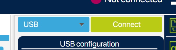
- Choose USB as the connection method (top right) and click Connect.
- Open the Erasing & Programming page (left sidebar).
- Next to File path, click Browse and select the
.binyou just downloaded. - Tick Run after programming and Verify programming.
- Click Start Programming and wait for it to finish.
- When it completes, click Connect again over USB, then do the Clearing the DFU boot flag step below so the device boots into the new firmware.
Clearing the DFU boot flag (Option Bytes)
Clearing the DFU flag with ST’s free programming tool tells the device to boot into its normal firmware instead of staying in the bootloader. This is a normal final step after a manual Windows flash. On macOS / Linux it is only needed in the rare case the Stuck in DFU? Restore Boot button doesn’t bring the device back.
- Install STM32CubeProgrammer from ST’s website and open it.
- With the device still connected over USB-C, choose USB as the connection method (top right) and click Connect.
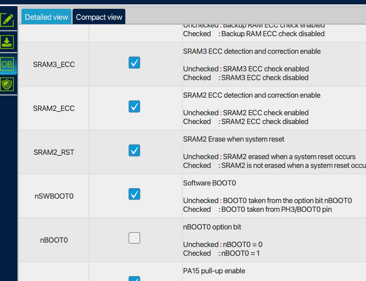
- Click the OB (Option Bytes) icon in the left sidebar and expand User Configuration.
- Scroll to nSWBoot0. Make sure nSWBoot0 is checked and nBOOT0 is unchecked.
- Click Apply. The device should now boot normally on its next power cycle.
Preparing for long-term deployment
Confirm the flashing-cyan LED turned off on its own (GPS fix acquired, clock synced). Replace the cover and hand-tighten the six screws in a star pattern — do not use an electric drill. For long deployments, apply Loctite 242 or 243 (medium-strength blue threadlocker) to the first 2–3 threads of each screw. Mount the collar with the solar cell facing up (upper hemisphere) for the best charging yield.
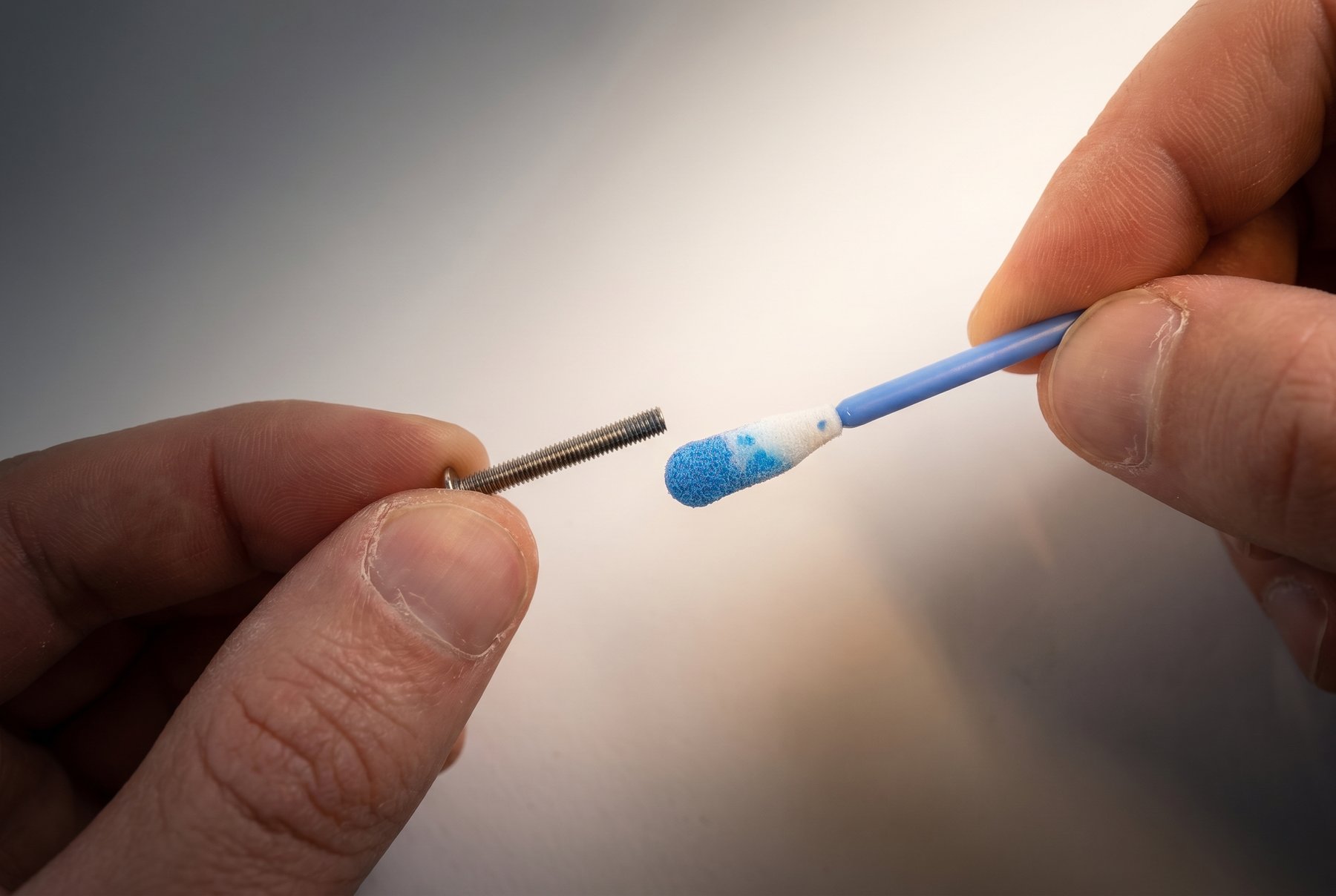
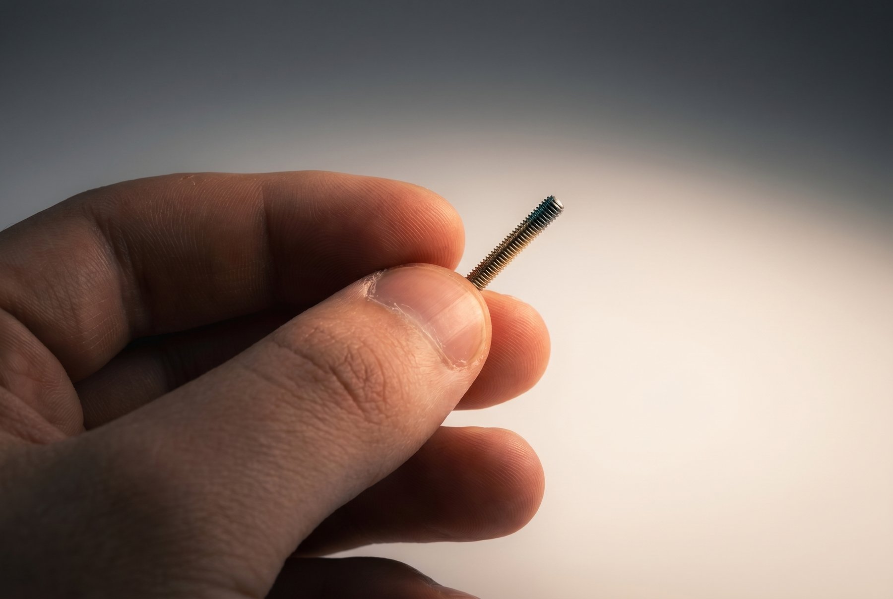
Use Loctite 242 / 243 (medium-strength, blue), not stronger grades. Avoid Loctite 263, 271, or 277 (red, high-strength) unless the device is a one-time-use deployment you do not plan to recover. Red threadlockers typically require heat and significant force to break, and can damage the polycarbonate or strip the inserts during retrieval.
Retrieving from the field
When you bring a device back from a deployment, follow this order so you don’t lose data and can re-deploy cleanly.
- Open the enclosure (six cover screws). Take care if you Loctited — 242 / 243 should release with steady hand pressure, but go slowly.
- Slide the side switch to OFF.
- Remove the SD card.
- Inspect the gasket and the inside of the housing for moisture or debris.
- Charge the device for the next deployment if needed.
Reading the data
Insert the SD card into your computer and use the metadata parser on the website to view what’s on it. From there you can also access the audio and accelerometer channels:
- SD Card — the on-site parser. Open the page, point it at the card, and explore the recorded data.
- Cloud Data — if your device also reports over the network, your bulk telemetry export lives here.
Sensor axis map
The onboard accelerometer and magnetometer report values along fixed device axes. Use this reference to interpret raw motion and orientation data in the context of how the collar is worn on the animal.
Both sensors share the same body-frame X/Y/Z axes. The accelerometer WAV files (/accelerometer/…) and the magnetometer rows in METADATA.CSV (mag,x,y,z) all use this convention.
Known limitations & in-progress features
CollarID Mk II is in active development. This is the canonical list of features that are partial, not yet shipped, or configuration-constrained.
In progress / not yet functional
- Satellite uplink and remote drop-off — in development; drop-off is in pilot. LoRa Lost Mode has shipped and is configurable under radio settings.
Current scope
- Microphone and accelerometer data are stored locally only — both write to the SD card and are retrieved on recovery; never transmitted over LoRa.
- Particulate sensors are not in default units — available on request; their use requires the outer shell to stay relatively scratch-free.
Platform constraints
- Repopulating LoRaWAN settings from the server is available only on the web configurator (not the mobile apps), and only for devices configured to talk to the CollarID gateway server.
- macOS + Chrome is the recommended environment for the configurator and firmware updates. Other combinations may work but are less battle-tested.
- The radio’s wireless update needs reasonably current firmware on the device. A main processor that is behind can be brought up to date over USB-C; a radio that is behind cannot be updated in the field at all and has to come back to us (see Updating firmware). This affects a small number of early pilot units.
Working with the team. CollarID is co-developed with researchers whose deployments carry unique constraints. Share your intended schedule with us so we can validate it in the lab first — it catches edge cases the configurator’s own validation doesn’t yet cover.
Troubleshooting
Boot animation keeps looping with a green flash
The SD card scan is failing. Power off, remove the card, reformat as exFAT, re-insert, and power on. If it continues with a known-good freshly formatted card, contact the team.
The status LED is flashing red
A sensor or subsystem failed the device’s power-on self-test. To find out which one, put the device in BLE mode and connect it to the Pre-Flight Check page — it names the failing part. The configurator shows the same warning when you connect. Contact the team with the serial number, what it names, and when the red flash first appeared.
The flashing-cyan LED never turns off
The device is searching for a GPS fix — bring it outside under open sky. After 10 minutes it gives up (LED off, not flashing) and runs its schedule unsynced from world time; it resyncs at the next GPS sampling interval.
BLE doesn’t appear in the configurator
- Confirm the status LED is steady cyan (not flashing). Flashing cyan means GPS, not BLE.
- Re-trigger BLE with a magnet swipe or a fresh-SD-card boot.
- On web, use Chrome or Edge — Firefox and Safari don’t support Web Bluetooth.
- On mobile, confirm Bluetooth is enabled and the CollarID app has permission.
Charge LEDs don’t light when I plug in USB-C
- The cable may be charge-only — try a different USB-C cable, ideally one from a phone or tablet.
- The port has no pass-through — confirm the cover is off and the cable is fully seated.
- Try a different power source.
Points are missing from the map
Usually nothing is lost. Radio messages go astray for ordinary reasons — the animal was out of range, or a gateway was down — so each collar keeps roughly a month of its own transmissions in reserve. When the server notices something never arrived, it asks the collar to send it again, and the gaps fill in over the following hours or days without you doing anything. Longer outages, such as a gateway being offline for a week, refill gradually so as not to drain the battery. If a gap is still there after a week, or the collar has stopped reporting altogether, get in touch. Nothing that reached the SD card is affected either way — the full record is still on the card at recovery.
My schedule doesn’t seem to have saved
The schedule commits when the steady-cyan LED turns off, ~10 s after you disconnect. If you closed the configurator or lost BLE mid-edit, reconnect and re-apply. The card-resident schedule is the source of truth.
Still stuck? Open a support request →